All boat owners have tales of woe about electrical problems aboard their vessels. The salt-laden marine environment mercilessly attacks electrical wiring and devices. It makes good sense to prepare ourselves with the tools and know-how to improve the reliability of our expensive electrical and electronic equipment. Building on the skills that I obtained as a diesel generator mechanic in the U.S. Air Force Reserve and further refined by 14 years of life aboard, I’d like to share with you my tips and techniques.
 |
|
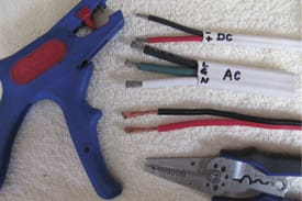
Properly terminated wiring makes a better, more reliable |
Getting to work
A good first project is to go over your vessel and remove each running light lamp. (Be sure to turn off the power first.) Brighten up the terminals on the lamp and the lamp socket with small stainless steel or brass toothbrushes, carefully removing any visible corrosion until the terminals and sockets are clean. Apply a thin coating of silicone grease to the lamp base and reassemble it. If vibration has worn down the one or two connections on the lamp base, creating an intermittent connection, simply build up the connection with a drop or two of solder. Turn on the power after reassembling the light and make sure it still works.
Next, unplug all electrical wiring on your radar, chartplotter, GPS, radios, instruments, etc., and clean away any corrosion. Apply a thin coat of silicone grease and reseat the cables a couple of times, ensuring that they are fully seated. Again, power up the equipment and check it out.
Be on guard to identify any bare copper wire, that is, any copper wire that is not tinned. Your vessel should have only marine-grade wiring in which the copper strands are coated with tin to provide a measure of corrosion protection. Replace any non-tinned wiring with marine-grade multi-strand tinned wiring such as Ancor. Do not use solid conductor wire, as vibration on board will cause the copper to work-harden and to fracture.
Splices should be avoided if at all possible. If unavoidable, then make up a soldered joint which should be constructed as follows:
Strip at least one inch of insulation from the ends of the wires to be joined. Use a proper wire stripper, and not a pocket knife. If you cut off any of the wire strands, then start over and do the job properly. The conductors should be bright silver colored, indicating tinned wiring in good shape. If copper-colored or black, stop now and scrap the wire as it is unacceptable. Replace it with new marine-grade multi-strand tinned wiring of the correct color code. Put a small amount of rosin soldering flux on the bare wires and twist them together to obtain a sound mechanical joint. The extra soldering flux will assist in removing oxidation, the formation of which is accelerated in the marine environment. Apply the hot soldering iron to the joint and apply the solder to the heated wire, not to the soldering iron. Apply sufficient solder to wet the joint thoroughly, then remove the iron and allow the joint to cool while not allowing it to move. When cool, the joint should be shiny. A dull color indicates a cold solder joint and must be reheated.
Insulation of the joint will be determined by its location. In a dry location self-amalgamating electrical tape covered with heat shrink insulation or vinyl electrical tape is sufficient. If in a wet location such as exterior wiring or in the bilge, then adhesive-lined heat shrink insulation is highly recommended. Heat the adhesive-lined heat shrink insulation until a bit of adhesive is squeezed out the end of the insulation, indicating a void-less seal. Place the heat shrink insulation over the wire before soldering the joint, and remember to keep it far enough away while soldering the joint that it doesn’t start to shrink too early!
The present color code for direct current wiring is red for positive and yellow for negative. The old code is red for positive and black for negative, and there is still a lot of the old color-coded wiring in service. The color code for 120 volt alternating current wiring is black for active and white for neutral. (In Europe’s 220-volt 50-Hz service, active is brown and neutral is blue.) Green, or green with a yellow stripe, is the color for earth or ground and must not be used for any other service. Be mindful of these color codes, but don’t assume that they have been correctly observed. Always treat a circuit as being live until proven dead.
This is worth repeating: When beginning any electrical work, always place one hand behind your back or in a pocket. This will prevent the establishment of a current path from one hand through your heart and on to the other hand, should you touch a live circuit.
Wire terminals should also be the tinned type, and not bare copper. Use only the ring type and not the fork type, to prevent accidental disconnects. A good crimping tool is an absolute necessity, one that will not release until the terminal is fully crimped. Wire crimpers that merely indent the terminal are not to be trusted. The shanks of the terminals must be insulated except those used in grounding systems. Note that solder must not be the sole means of mechanical connection of a terminal. Terminals should be fully crimped and then soldered. The only exception is battery cable lugs with a solder contact length of not less than one and a half times the diameter of the cable.
Twelve-volt plugs and sockets
Much trouble and aggravation aboard can be eliminated by systematically replacing all non-marine 12-volt plugs and sockets with the excellent plugs and sockets made by Marinco. These are especially designed for the marine environment, are water resistant (not waterproof, however), and have the added features of an internal, replaceable fuse in the plugs, and a locking feature to prevent the plug from accidentally pulling out of the socket. The plugs are a bit difficult to wire up, but well worth the effort. After wiring the sockets, a wad of Duct Seal or Coax-Seal should be wrapped around the aft end of the socket to weather-proof the wiring connections if they are exposed to the elements.
Battery terminals
Inspect your batteries for loose terminals and corrosion. The positive and negative posts have different diameters, so make sure that your battery cable terminals are correctly sized. Clean off any corrosion products with a mixture of sodium bicarbonate (baking soda — not baking powder) and water and a stainless steel brush. Place chemically treated anti-corrosion felt washers over the battery posts before reinstalling the battery terminals and cables. These are available at most service stations and auto parts stores, and they really are effective. Replace them every two years or so.
Extreme-duty applications
In this category are anchor windlasses, electric winches, bilge pumps, solar panel connections, wind generators and shore power connections which are exposed to the weather or to high-moisture areas. The electrical connections to these devices require extra protection. Apply an anti-oxidant film such as Ox-Gard to the conductors to be bolted together. Where the connections cannot be covered with electrical tape, spray them liberally with CRC Soft Seal. Carefully mask the surrounding area before you begin spraying, as Soft Seal is as ugly as it is effective. Crimped terminals and butt splices should be of the heat shrink adhesive-lined type. Seal wire entry points with an application of Duct Seal, which is like industrial-strength modeling clay.
Protection against vibration and chafe
Use nylon wire ties liberally to secure wiring so that vibration will not work-harden the wiring at the terminal crimp and cause failure. The plain white nylon wire ties are fine for interior use, but always use the black wire ties for any location exposed to sunlight as they are UV stabilized.
Protect wiring from chafe with grommets where the wiring passes through bulkheads or around sharp corners. A length of water hose over a wire can provide additional chafe protection. A split length of hose can be wrapped around already installed wire or wiring bundle and secured with wire ties.
Observing polarity
When using socket and spade terminals, for example, on lighting fixtures which must be removed for service, a good practice is to put the socket on the positive lead of the supply wire (and on the negative lead of the fixture wire). This ensures that correct polarity is observed when the fixture is reconnected; especially important on polarity-critical LED or cold cathode fluorescent fixtures.
Installing new equipment
When installing new electrical gear, follow the instructions in the device’s installation manual to select the correct size conductors, or consult a guide such as the excellent one in the West Marine catalog. Remember that conductor length is the “round trip” length to and from the device (positive and negative leads) and not just the straight-line distance. Always add 10 percent to the actual measured length to allow for a bit of error and for terminating the wiring. Add additional length for removing the device, also. If the conductor sizing guide indicates a between size, select the next larger conductor. Wiring should always approach a switch or circuit breaker from below to prevent water from running along the wire into the switch or circuit breaker.
After installing the connectors and before applying power, use your digital multi-meter to check for continuity and short circuits in each conductor. For alternating current circuits, it’s also a very good idea to acquire a plug-in type circuit checker which will indicate problems such as open earth circuit, open neutral, open active, reversed active and ground conductors, or reversed active and neutral conductors. Use this device each time a wiring change aboard or connection to shore power is made. They are very inexpensive and may save your zincs or even your life.
Tip: Leave a circuit checker plugged into an outlet so that if someone changes your shore power connector to an incorrectly-wired pedestal, you will have an indication of it, hopefully before any damage has occurred.
Fuses and circuit breakers
The glass tube automotive-type fuses are available in “slo-blo” and fast blow types. The slo-blo fuses are used where starting currents exceed running currents such as induction motors. Be cautious with “in-line” fuse holders that are provided with some electronic equipment as they are invariably cheap and likely to fail. Carefully inspect each one aboard for evidence of over-heating and corrosion. Replace any suspect fuse holders with high-quality marine-grade fuse holders. Check the condition of a fuse with the ohm meter function of your digital multi-meter. A bad fuse will show very high resistance and a good fuse will show less than one ohm resistance. Replace any fuse with a resistance greater than one ohm.
Circuit breakers should be sized according to the equipment that they protect. The normal load should be no more than 80 percent of the rating of the circuit breaker; e.g., an 80-amp load should be protected with a 100-amp breaker.
Finally, if you don’t already have one or more aboard, now is the time to install a Ground Fault Circuit Interrupter (GFCI), also known as a Residual Current Detector (RCD). A combined circuit breaker (two pole) and GFCI should be installed between your shore power connector and the distribution panel. This is a handy way to add the protection of having a circuit breaker in both the active and neutral conductors, as your distribution panel probably has only a circuit breaker in the active line. Before tackling an electrical project, make a check list to prompt your memory: are sources of electrical energy safely disabled; are the required tools and materials on hand, do you have a stand-by assistant, etc.
Harry Hungate and his wife, Jane Lothrop, have cruised more than 40,000 miles aboard their Corbin 39 cutter, Cormorant, since moving aboard in Annapolis, Md., in 1997. They crossed the Indian Ocean and Red Sea in early 2009 and spent the winter of 2010 in Gaeta, Italy.