After enjoying the benefits of an automatic identification system (AIS) receive-only unit aboard for the last four years, we recently upgraded to a full transmitter-receiver or transponder. We chose the ACR Electronics Nauticast-B model 2680. A thorough Internet search rewarded us with a price of $500 plus shipping.
First, unpack the AIS, making sure that you have received the transponder, the GPS antenna and mount, the VHF antenna and mount, the cable assembly, and the CD with configuration program Link2AIS. This software will not run on Windows 7; however, a CD with the beta version for Windows 7 was available through ACR dealers as of September 2011.
Installing the transponder requires a bit more work than the simple receiver, as not only VHF and GPS antennas and data and power cables must be wired up, but also the configuration cable to a computer must be connected. Additionally, this AIS transponder requires a separate momentary-on push-button switch to turn off the transmitter to operate in “silent” or “listen only” mode.
Along with the usual collection of hand tools, I needed the following to complete the job: RTV silicone sealant to weather-proof the coax ports on the GPS antenna; an electrician’s snake to route the coax cables through my stern arch (a length of very heavy monofilament such as used in weed-whackers will serve handily); a TNC female connector for RG-58 coax; wire lubricant (KY works wonders!); and a momentary-on single pole push-button switch.
First determine a location for the AIS transponder. It need not be visible, as it has no display, but it must be in a dry place that provides access to the various cables connected to it. Mount the transponder to a bulkhead using four self-tapping screws.
 |
|
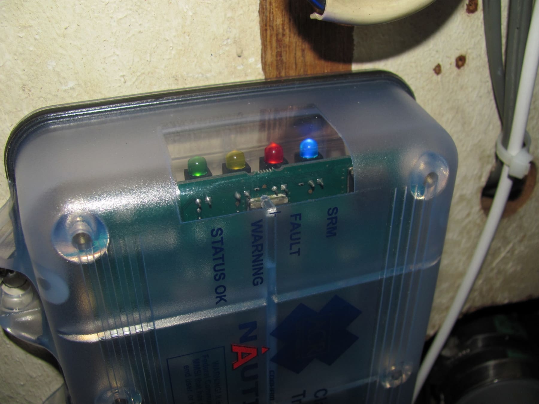
LEDs on the ACR NauticasB AIS unit will indicate proper installation of the unit. |
Install the GPS antenna, again observing as best as possible the required spacing from other antennas. The GPS antenna has the standard one-inch NPT (1”-24) female thread, and the mount is the surface type. I substituted a one-inch rail mount. I had originally thought that I could simply obtain the GPS signal from the multiplexer that is required with my Raymarine C120 multipurpose display, but the ACR transponder uses an active antenna with the GPS receiver built in to the transponder. Unlike simple AIS receivers, most AIS transponders require their own dedicated (non-shared) GPS antenna and receiver due to timing issues with transmission slots. I mounted the GPS antenna near my existing Raymarine GPS.
The ACR GPS antenna comes with 15 feet of coaxial cable with an SMA female connector already installed. A TNC female to SMA male adapter is provided to connect to the AIS transponder. If you have to cut off the SMA connector in order to pull the coax through a conduit or cable way, you can replace the SMA connector or go directly to a TNC female connector, either crimp-on type, soldered type or one of the twist-on connectors from Centerpin Technology. Check their website for local sources. Your local Radio Shack store is a good source of crimp and soldered TNC connectors.
Install the VHF antenna, again observing as best as possible the required spacing from other antennas. The VHF antenna need not be mounted on the masthead, as you do not need extreme range. (Our antenna is on the stern arch and is 12 feet above the water; we receive signals from ships more than 50 miles away.) I used my existing disc-cone broadband antenna that I have been using on my AIS receiver with excellent results. A length of marine-grade RG-58 50-ohm coax and two PL-259 coax connectors and adapters connected the antenna to the transponder. By the way, when in port this antenna serves as a very good television antenna, as it has no nulls. I just swap the 50-ohm coax for a 75-ohm coax for television use.
Place an in-line 3-amp fuse in the power cable and connect the power cable to the ship’s 12-volt DC system via a panel-mounted circuit breaker. We have our sonar and AIS on the same circuit breaker. If additional length is required, increase the wire size to minimize voltage drop. Get the polarity right: red is positive and black is negative. Get it wrong and you will need to purchase a new transponder.
The data cable is labeled RS-422. It has four conductors, of which only two are needed to feed the data to your multifunction display. I chose the yellow (RxA) and orange (TxA) pair and taped the other two out of the way.
A single pole momentary-on push-button switch is required if you want the ability to transmit a safety related message or to turn off the transmitter to operate in the “silent” or “listen-only” mode — you must choose one or the other or none with the Link2AIS configuration software. This is of special interest to those crossing the Indian Ocean and Gulf of Aden.
Interfacing the AIS withan MFD
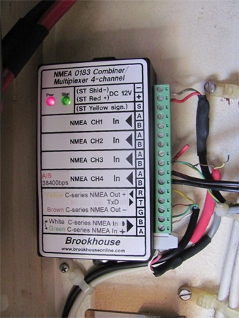
Chartplotters more than just a few years old were not designed for AIS, so will require a multiplexer to allow the connection of more than one signal to the single NMEA high speed “data in” port. I used the Brookhouse multiplexer on our Raymarine C-120 multifunction display. I removed the two AIS receiver data wires from the multiplexer and replaced them with the two data wires from the ACR AIS transponder: Yellow (RxA) from the transponder to terminal B on Channel 4 in, and orange (TxA) to terminal A on Channel 4 in. If your equipment is different, then get out the manuals and spend a few hours reading up on how to do it.
Commissioning the AIS Transponder
Following the instruction manual, load the Link2AIS configuration software on your computer. It loaded easily on my old laptop running Windows XP Pro, but refused to load on Jane’s new notebook running Windows 7 Pro. (A call to ACR-Europe yielded a Web link where I could download a beta version which worked fine.) Boot up the software and connect the data cable, labeled RS-232, from the AIS transponder to your computer’s serial port. (Use a serial to USB adapter if your computer has no serial port.) Power up the AIS transponder. Select “new connection” and choose Com1. The screen should show “connected.” If it doesn’t, then select Com3 or such until the connection is made. For AIS transponders purchased in the U.S., the dealer will already have your Maritime Mobile Service Identification (MMSI), ship’s name and call sign entered in its database, but you will have to enter the location of the GPS antenna and select what function is required of the push-button switch. Enter the location of the GPS antenna in whole meters as no fractions are allowed. Select “Save to AIS” and the job should be complete. Close the configuration program and disconnect the serial cable, as it is not required for operation of the transponder.
Power up the AIS transponder while looking at the four LEDs on the top. All four LEDs will flash twice, then the yellow LED will stay lit until a GPS fix is obtained, then the green LED will light indicating that the transponder is operating successfully.
Have a nearby AIS-equipped vessel check your information to confirm it is being transmitted correctly. It took me a couple of iterations to get it right.
————————
Harry Hungate and his wife, Jane Lothrop, have lived aboard and cruised on their Corbin 39 cutter, Cormorant, since departing Annapolis, Md., in 1997. They plan to cross the Atlantic Ocean from Gibraltar at the end of 2011.