There are two approaches to marine exhaust setups. “Wet” exhausts, the type that inject seawater into the exhaust gases to cool and quiet them, are by far the most common. Dry exhaust systems, on the other hand, utilize a stack or pipe not unlike those seen on large commercial vessels and trucks for that matter. The reason for wet exhaust’s popularity, however, is not because of its reliability. It is, in fact, quite the contrary: Wet exhaust systems are known not only for their propensity for failure, they are also renowned for their complexity and expense. To be fair, however, nearly all of the failures I’ve seen are a direct result of poor design and incorrect material selection.
If wet exhaust systems are so trouble prone and costly, then why, you might ask, are they so common? There’s essentially one reason — vessels need to be designed around a dry exhaust. The exhaust gases, which can be as hot as 1,000° F, must be conveyed from the engine room to a high point on the vessel as directly as possible, which usually necessitates passing them through saloon, galley or other living areas, taking into consideration both temperature and acoustic issues. Conceiving and building a structure that incorporates this “plumbing” is no small task and it needs to be taken into account early on in the design process. Builders who utilize dry exhausts know this all too well.
 |
|
If the injection angle is too shallow, water may back up. |
The wet system
Wet exhausts, on the other hand, carry no such requirements and it accounts for their popularity; they are flexible designs that allow builders the freedom to place them without the concerns that accompany dry exhausts. However, they have their own set of concerns and requirements.
Because the water cools the exhaust gases shortly after they leave the engine, they can be routed aft and low through the vessel and to the transom, or to an underwater discharge comparatively easily and with little concern for heat generation or insulation using hose or fiberglass tubing. While that sounds straightforward enough, accomplishing it in a manner that is reliable, safe and meets engine manufacturer requirements can be quite challenging.
 |
|
Unlike this one, wet exhaust runs between the injected elbow, and the water-lift muffler must always be a downward slope. |
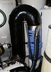
Fundamentally, the goal of a wet exhaust system is to cool and expel exhaust gases while preventing water from backing up into and ruining the engine. This usually involves utilizing an injected elbow or riser, a device that injects water into the exhaust gases. An integral aspect of a wet exhaust system involves the injected elbow’s height above the vessel’s LWL, or loaded waterline. The required height varies from engine manufacturer to engine manufacturer; however, in the case of Cummins Diesel (their engine installation manual is a respectable 161 pages long, and the section on exhaust systems alone fills 17 pages) the bottom of the exhaust manifold or turbocharger outlet must be a minimum of 12 inches above the LWL. If this is not the case for a given design, then a riser may be added to increase this height.
Whichever approach is used, a number of caveats will apply. Water injected into the exhaust gas stream should be in a diffused or spray pattern through a series of holes that are about five-sixteenths of an inch in diameter (about the size of a pencil), and the injection should be parallel to rather than perpendicular with the flow of exhaust gases. The number of holes is a function of the water flow rate. In this manner, the water surrounds the exhaust gases, cooling them evenly and avoiding hot spots that could lead to hose or fiberglass tube failures.
 |
|
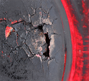
Exhaust hoses can overheat, burn and be pierced if water flow to the exhaust system is interrupted or if the injection angle is too shallow. |
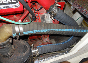
Unless a water-lift muffler is used (more on this below), the flow of water from the point of injection until it exits the vessel must be on a continuous downward slope (quoting Cummins’ guidelines again) of two degrees or one half-inch of drop for every 12 inches of run. The angle of the elbow itself is especially critical: 15 degrees from horizontal is the bare minimum for Cummins, others specify 25 degrees; more is better and vertical is best. If the angle is too shallow, not only is there a risk of water backing up into the elbow through the turbo or exhaust manifold and exhaust valves and into the cylinders, the injection water also tends to pool in the bottom of the hose or fiberglass tube, leaving the top exposed to hot exhaust gases, which leads to localized overheating and possible failure. Counterintuitively, this problem often manifests itself at lower rpm, when less water is being pumped by the engine.
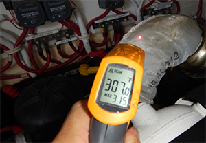
Temperature guidelines
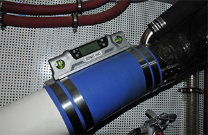
While on the subject of temperature, in order to comply with ABYC guidelines, no portion of the exposed exhaust system — dry or wet — may exceed 200° F under any operating conditions, and dry portions of the exhaust system must be no closer than six inches to combustible materials such as wood or fiberglass. Typically, in the sea trials I conduct I rarely see the wet portion of an exhaust system with a temperature exceeding 150° F; anything higher than that is cause for concern. All wet exhaust systems should be equipped with high-temperature alarms. It’s a requirement for ABYC compliance, and these should be tested annually.
 |
|
All exhaust components should be insulated or protected to prevent touchable surfaces from exceeding 200° F. This elbow’s insulation is insufficient to meet this goal. |
Clearly, this means that the dry portion, the section before the water injection elbow, requires insulation or at the very least a guard or shield, which must cover all surfaces that exceed this temperature. The insulation itself must be durable and fireproof and it must resist absorption of fuel, oil and coolant. Had I not seen it with my own eyes, I never would have believed it possible, however I once witnessed exhaust system insulation catch fire moments after it had absorbed spilled coolant. Obviously, fuel and oil are of equal or greater concern.
If the necessary rise above the LWL and the continuous downward slope cannot be achieved in an exhaust system installation, an alternative exists. The aforementioned water-lift muffler provides installers an option for achieving a compliant wet exhaust. The water-lift muffler provides an artificial waterline of sorts to which the exhaust is then referenced. However, the water lift’s own internal resting waterline must still be a minimum of 12 inches below the bottom of the engine’s exhaust or turbo outlet, and the discharge from the water-lift muffler must still form a riser that is a minimum of 12 inches above the LWL when measured to the bottom of the riser hose or tube.
Exhaust system design and installation compliance is critically important. Never assume it’s correct simply because it works, or because the vessel is new.
Steve D’Antonio is an ABYC-certified master technician and owns Steve D’Antonio Marine Consulting.