Boats roll. Even catamarans will roll to some degree (and never recover if pushed too far). A boat’s roll behavior when underway will vary depending on whether it is running on a plane or at displacement speed. Roll can be most disturbing when at anchor. The one thing we can be sure of is that there will be times when we will wish that our boat would stop rolling.
A number of different mechanisms are at our disposal in our quest for improved stability. Depending on the design of the hull and the boat’s cruising speed, bilge keels or similar fixed appendages can help when we are underway, or a steadying sail may help. We may be able to reduce roll when underway by manipulating the rudder or by using the boat’s trim tabs. (Automatic counter-rudder control has been tried on some vessels, including Navy destroyers; automatic systems that use special trim tabs are available for use on some boats.)
Servo-controlled anti-roll stabilizing fins are by far the most popular and proven way to stabilize a vessel when it’s underway. However with few exceptions these devices won’t help when we are at anchor, a time when we may especially prize stability.
Roll-control devices that are effective both when underway and at anchor are generally limited to approaches. One method involves towing paravanes from booms extending from the sides of the hull and replacing them with flopper stoppers when anchored. The other strategy is an anti-roll, ballast-shifting system using water tanks, in which the flow of fluid from one side of the vessel to the other is timed to occur in opposition to the rolling force. Such systems, however, are not usually practical for small vessels due to the magnitude of the mass required (1.5 percent to 5 percent of the displacement of the vessel) and the space the mass would occupy.
While the menu of roll-control systems that can meet our desire for control at any speed seems very limited, a look back about 100 years will disclose an idea that has now become a practical solution: the anti-rolling gyro.
Like most modern inventions, the gyroscope has a long history, dating back to 1817 when it was invented by Johann Bohnenberger, professor of mathematics and astronomy at the University of Tubingen. Anyone who has studied mathematics will recognize the name of one of its earliest proponents, Pierre-Simon Laplace. If you have visited a museum where a pendulum is exhibited that demonstrates the rotation of the earth, you know of another gyro experimenter, Leon Foucault, who gave this strangely behaving device its name, the gyroscope.
One of the early practical uses for the gyroscope was the gyrocompass, developed in Germany by Hermann Anschutz-Kaempfe between 1903 and 1908 (the name Anschutz will be found today on gyrocompasses and autopilots on many large yachts and ships).
Gyros for stability
Elmer Sperry designed a gyrocompass in 1908 and then applied the gyroscopic principle to the challenge of stabilizing a ship. The unavailability of practical servo amplifiers made it necessary for Sperry to take a direct (brute force) approach in using a gyro to control the roll of a vessel. His first large-scale system, comprised of two gyro wheels having a total mass of some 60 tons was installed in a new U.S. Army troop ship, USS Henderson in 1917. The Sperry Gyroscope Company continued to develop similar direct-acting stabilizing gyros culminating in some truly massive triple-rotor installations such as the 650-ton system installed in the Italian liner Conti di Savoia in 1932.
There’s a song on the Lenny Kravitz album, Mama Said, that comments at length on the fact that “what goes around comes around.” So it is with gyro stabilization for vessels. Work begun almost 100 years ago has led directly to a system that will stabilize our boats and yachts, when underway, when at anchor or when tied to a dock.
The current generation of direct-acting gyrostabilizers was introduced by Mitsubishi as the Anti-Rolling Gyro (ARG) in 2004. A more refined system, the Seakeeper Model 7000 Gyro Stabilizers, from Seakeeper in Solomons, Md., was announced about 18 months ago and is now being installed on boats. The Seakeeper, like the ARG and Sperry’s systems of the early 1900s, reduces a vessel’s rolling motion by applying a force to the hull that directly opposes the force that is working to cause the roll.
A classic gyro consists of a rotor, which is a mass rotating on an axle. The axle’s bearings are mounted within a gimbal, an external support ring that is in turn supported by an additional set of bearings so that it can rotate about an axis at 90 degrees to the axle that supports the rotor. In most gyros the first gimbal is supported in turn by a second gimbal. The gyroscope’s behavior relies on the principal of angular momentum.
A particularly strange aspect of gyros is a phenomenon called gyroscopic precession. In precession, a force applied to the axis of the rotor in one plane will result in the creation of a force in a plane displaced by 90 degrees. For example, if a horizontal rotor is turning clockwise on a vertical axle and a force is applied to the axle in a direction that would tilt the rotor downward at the 9 o’clock position, the precession phenomenon will result in a force that will act to deflect the rotor downward at the 12 o’clock position, 90 degrees from the point where the disturbing force was applied.
In a fully gimbaled gyroscope, the rotor’s axle (the spin axis) is mounted in a gimbal ring, which is, in turn, supported in a second gimbal ring with bearings positioned at 90 degrees from the spin axis. This is then supported by bearings mounted to the gyroscope’s frame or outer housing. In a toy gyroscope the outer frame is often placed on a sharp pivot point, on which the spinning gyro will stay balanced until the rotor speed decreases to the point where the friction in the bearings overcomes its inherent stability.
Modern anti-roll gyros
The gyro that Mitsubishi and Seakeeper use to stabilize a boat is somewhat simpler than the gyro used in a north-seeking gyrocompass or in an aircraft attitude indicator. These roll-stabilizing gyros have spin axis bearings and only a single-gimbal system. The spin axis is vertical and when the vessel is at rest the rotor spins in a horizontal plane. The gimbal axis is, as usual, at 90 degrees to the spin axis with its bearings attached to the vessel’s structure in an athwartship position.
When the vessel rolls to port, the force that is applied to the spin axis acts downward at the 9 o’clock position on the rotor. The precessed force that results acts downward at the rotor’s 12 o’clock position. This force causes the rotor’s axis to tip forward toward the bow of the boat. A linkage connected to the gimbal aft of the transverse bearings is moved forward by the rotation of the gimbal. This forward motion can then be applied to the hull structure as a lifting force that will work against the force that was attempting to roll the vessel to port. A starboard rolling input to the hull will result in an opposite set of reaction forces that will act against the rolling motion.
Making the gyro stabilize the boat takes a bit more work, simply connecting it to the hull with solid linkages would result in poor performance except at certain roll-force input frequencies and a series of rather solid shock inputs to the system as the gyro responds to the roll-force inputs. Seakeeper has incorporated a sophisticated computer-controlled system to couple the moving gyro to the boat’s hull. The system allows the gyro to dampen roll inputs over a range of frequencies much wider than would be possible with a simpler mechanically dampened connection to the hull. It will also protect the gyro and the structure from excessive reaction-force inputs such as when the vessel encounters a sharp pitching movement.
The Seakeeper Web site includes a video that graphically demonstrates the very active rocking motion of the gyro housing as it reacts to roll inputs, alternately pulling and pushing on the hull’s stringer system. According to Seakeeper’s data sheet the correcting force applied to the vessel’s hull by the approximately 950-pound gyro can be as high as 5,300 pounds. Seakeeper requires that the gyro system be attached to the hull using high-strength adhesive that captures both sides of the hull stringers, not mechanical fasteners. This ensures that the attachments are stressed in shear over a wide area and therefore able to resist the reversing cyclic loads created as the gyro responds to each roll movement of the vessel.
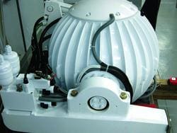
A 10,000-rpm rotor
The gyro wheel in the Seakeeper system is housed in a partial vacuum in a spherical container. The sealed sphere is designed to minimize windage loads that result from its 10,000-rpm speed and to ensure that the bearings are well protected from the marine environment. The system’s power drain is about 3 kw during the approximately 45 minutes it takes for the rotor to reach full speed, at which time the power demand decreases to about 1.5 to 2.0 kw. A genset will be needed to keep the gyro operating when underway or while anchored; shore power can be used at a dock. The manufacturer reports that the operating noise level is modest but recommends that it be installed in the engine room or in a suitably sound-shielded space. The gyro can be located virtually anywhere in a vessel, but not forward in a high-speed boat.
As effective as these systems are, roll stability, whether achieved with active, servo-controlled fins or a gyro, does not come cheaply. Either system will likely cost about $50,000 installed (the gyro will likely cost more than a fin system’s components but will be less expensive to install and maintain).
Contributing editor Chuck Husick is a sailor, pilot, flight instructor, electrical engineer and rides a mean bicycle.