Our owner-completed Corbin 39 cutter is beautifully finished inside and out, and came fitted with many desirable features, save one: the engine was not enclosed in a sound-absorbing housing. In fact, the noise from the engine reminded me of my childhood, driving my father’s 1933 Farmall model F-12 tractor. While hauled out for a major refit in New Zealand, I decided to construct a hush box for the engine. The installation manual for my Yanmar model 4JH2E 50-hp four-cylinder diesel engine provided specific design info.
This project is fairly straightforward. You will need simple hand tools: electric drill and bits, screwdriver, self-tapping sheet metal screws, flat file to remove sharp corners, pop riveter and aluminum rivets, measuring tape and felt tip marker. The local sheet metal shop can provide the sheet aluminum and access to a sheet metal brake and shear. Sound-absorbing material such as Soundown is available from most chandleries.
 |
|
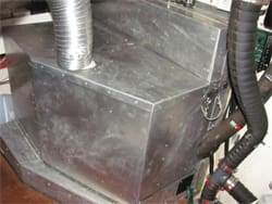
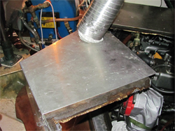
The air intake housing. |
 |
|
The hinged top allows access to the engine for repairs and maintenance. |
Even if you don’t plan to do all or any of the work yourself, this article will familiarize you with the process and provide a blueprint for your own engine hush box.
Designing the hush box
First step was to construct a rough outline drawing with dimensions of the space required. Easy access to service the engine was then sketched in. Remember that you have to check the oil level, add oil to the engine, replace the oil filter and fuel filter, and drain out the used oil, and you certainly do not want to have to dismantle the hush box to gain access to these items. An important consideration is that all of the panels will have to fit through the engine compartment door! An air intake opening will be required for the enclosure. Its design must incorporate two requirements: adequate air flow (both combustion and cooling) for the full speed operation of the engine, and sufficient baffling to prevent the engine noise from escaping.
Although the Yanmar installation manual stated that either aluminum or plywood could be used to construct the hush box, I opted for aluminum of two-millimeter thickness, as it was available at the nearby metal shop. Also, I reasoned that the finished product would be lighter than if I had used plywood. And, aluminum is fireproof and doesn’t need to be painted.
The aluminum panels were to be lined with Soundown (www.soundown.com), a sound-absorbing product about one-inch (25 mm) in thickness.
Installation
The base of the hush box is permanently fastened to the engine bearers and to the bulkhead with stainless steel self-tapping machine screws. I used Phillips-head screws whenever possible. Note that the athwartships base follows the curves of the hull. The various panels fit together with tongue and groove type joints to allow tool-less disassembly while maintaining noise-tight integrity. The tongue and groove joints were fabricated with strips of aluminum about one-inch wide and fastened to the panel edges with pop rivets. A hinged panel provides easy access to the alternator, coolant cap and tank, and engine oil fill and dipstick.
My engine is mounted “backwards” with a V-drive, so the transmission end of the engine is fitted with Soundown blankets to prevent the noise from escaping into the boat. Two blankets constructed of Soundown covered with vinyl fabric are attached with Velcro strips for easy removal to change the transmission fluid.
As the engine is now tightly enclosed, a ventilation system is required to carry away heat, and to provide cooling air for the alternator. A small 12-volt computer-type muffin fan is mounted near the hull (where the air is coolest) on the hush box base to provide forced air cooling to the alternator via flexible ducting. The fan is fused and draws its power directly from the alternator. This volume of air is ignored in the above sizing calculations.
Hot air from the engine hush box is discharged outside the boat via a Jabsco model 35770-0092 12-volt centrifugal blower. This is the commercial model rated for continuous operation at 250 cubic feet per minute. I cut a hole in the top panel of the hush box just above the alternator for hot air removal. Flexible ducting (used for venting clothes driers) connects this ventilating hole to the intake of the blower, and the discharge of the blower is ducted to a clamshell ventilator on the hull topsides. An on/off switch on the engine control panel and a separate fuse for the blower completes the circuit. The blower runs constantly while the engine is in operation, and I let it run for 10 minutes after shutting down the engine. The blower is somewhat over-sized for this job, so I inserted a restriction orifice on the blower intake to limit the throughput, basing the size of the restriction orifice on the amperage vs. volumetric flow curve in the instructions with the blower. The ventilation flow rate should be equal to the volume calculated for Qe (see sidebar, below) or about 150 cubic feet per minute. In hindsight I should have selected the three-inch blower instead of the four-inch one.
After all of the panels were finally cut to fit and trial-fitted on the engine, I removed them and with the use of contact cement, covered the interior of the hush box panels with one-inch thick Soundown. Remember to allow for the panel edges when sizing the Soundown sections.
I did not have the mounting devices or the seam tape recommended for use with Soundown when I originally built them, so after eight years of use, the Mylar exterior layer of the Soundown began to separate from the foam inner layers. This probably would not have occurred if I used the proper tape. To salvage the Soundown panels, I obtained thin perforated aluminum sheets and by using one-inch standoffs created from a quarter-inch aluminum tubing, I pop-riveted the perforated panels over the Soundown. The standoffs were easily made by marking a length of aluminum tubing at one-inch intervals, slowly turning the tubing with an electric drill, and cutting the tubing with a tubing cutter. A countersink removed the burrs from the tubing ends.
These perforated aluminum panels can also be applied to new installations to avoid the separation problem, and are a handy solution to separation problems in your existing generator and main engine compartments, as well.
I haven’t used a sound level meter to measure the hush box sound level, but our ears certainly can tell the difference.
———-
Contributing editor Harry Hungate and his wife Jane Lothrop have enjoyed their “hushed” engine aboard their Corbin 39 cutter, Cormorant, since 2002.
SIDEBAR: The air intake opening
The Yanmar installation manual was helpful in providing example calculations for sizing the opening for the air intake. The math is quite straightforward, but make sure that you get it right. Use this procedure:
Formula for ventilation air: Qv = 0.13 x maximum output horsepower for naturally aspirated engines and Qv = 0.15 x maximum output horsepower for turbocharged engines.
Formula for determining area of ventilation duct: S = Qv/V where:
S is the area of the duct in square meters.
Qv is the ventilation air in cubic meters per second.
V is the duct velocity, which should not exceed 10 meters per second. Note that this formula is for natural flow, while in fact, I have used both forced draft and induced draft blowers. So, the resulting duct size will be very conservatively oversized.
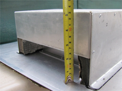
My final dimensions worked out to be eight inches long by two inches high for the air intake opening in the hush box panel. The engine is rated at 3,400 RPM continuous operation, but as I rarely operate my engine above 2,600 RPM, these numbers are indeed very conservative.
To calculate the volume of air to be exhausted by the engine compartment blower, subtract the air required for combustion from the ventilation air: Qe = Qv minus Qc.
Formula for air required for combustion: Qc = (Kt x Vs x N x C)/1,000 in cubic meters per minute where:
Kt is the volumetric efficiency of the engine (0.8 to 0.9 for normally aspirated engines and 1.3 for turbocharged engines).
Vs is engine displacement in liters.
N is engine speed in revolutions per minute.
C is a constant (1/2 for four-cycle engines).
The figures for my Yanmar 4JH2E 50-hp engine worked out to be Qc = 3 cubic meters per second and Qv= 6.5 cubic meters per second.
The air intake housing and its internal baffle were also lined with Soundown, so the final dimensions were increased accordingly. The intake housing and opening in the hush box was placed on the far side of the engine (the opposite side from the service side) and attached with aluminum pop rivets.